Current Issue

Our Partners
P3 1-2/2022 en
Optimal Creasing
Packaging Boards With Water-Based Barrier Coatings
Science & Technology

Water-based coatings / exact creasing is an IGF type project at Papiertechnische Stiftung (PTS).
Many food packaging applications require coated paperboard grades. Coated boards must have good creasability as a critical property for the converting processes. Creasing is done to prepare the material for folding and is performed simultaneously with die-cutting (creasing-cutting process). The board inclusive of its coating undergoes strong deformation during creasing, involving the risk that the barrier layer could be damaged or weakened. Although the creasing process is generally well-controlled for extrusion-coated and film-laminated boards, there are recurring problems with aqueously applied coatings. Especially, it is not clear which conditions are necessary for optimal creasing results.
Water-based coatings / exact creasing is an IGF type project at Papiertechnische Stiftung (PTS).
Project goals
The IGF project pursued two goals: One goal was to characterize in more detail the loads and strains of the material during the creasing process using a model based on the finite element method (FEM); the other goal was to develop recommendations on how to keep functional barrier losses as low as possible in the crease seam.
A number of specific measuring methods were envisaged in support of the first goal. They provided characteristic values for major input parameters. In order to achieve the second goal, systematic creasing tests were carried out on several board grades with different coatings in order to derive optimal creasing parameters.
In practice, the thickness (br) and immersion depth (h) of the creasing rules, and the width and depth of the creasing channels (bn and tn) at the make-ready are adjusted exclusively according to the board thickness (d). This is also true for paperboards with top and bottom coatings. Usual standard conditions are illustrated in Fig. 1 and Fig. 2. A far-reaching insight into the creasing behaviour of paperboard can be obtained by means of a crease area chart, which covers a systematic variation of the immersion depth and the creasing channel width.
Development of the FE model
The model was developed with the FE software LS-DYNA, which is well suited for the simulation of complex deformation processes. The creasing bar (rule) and the edges of the creasing channel (groove) were simulated by cylinder-shaped geometries with radii that were each time adapted to given practical conditions (refer to Fig. 4).
In a first step, the paperboard was divided into seven individual layers, and later on an eighth layer was added, which represented the coating. So it was possible to generate accurate results in terms of the internal loads and to study the effects caused by layer displacements. Since the creasing operation was defined by delamination between the layers, potential delamination levels were inserted between the outer layers of the material (layer 1, 2 as well as 6, 7) and the medium ply (layer 3-5). They had to be described with characteristic values regarding their maximum strength and stiffness both in plane and out of plane. The out-of-shear test stand shown in Fig. 2 and the optical strain field analysis shown in Fig. 3 were used for this purpose. Also, the internal bonding strengths in a Z direction were determined.
The practical creasing tests on the universal testing machine were evaluated by means of an optical strain field analysis and showed the expectable compression and tensile areas in the thickness direction. The material located under the creasing bar during the operation is compressed whereas the material in the sidewalls of the creasing groove is drawn apart. The highest compression takes place exactly under the tip of the creasing bar.
The results of the simulation are an exact match of the material’s behaviour in practice. Both the compressed areas under the creasing bar and the tensile areas at the top of the sidewalls can be seen in Fig. 4. Similarly, the picture shows the elongation results, which reflect different strain values in the various plies, or layers, of the paperboard in the creasing edges. The visual representation of the node shifts in the model is exaggerated and does not correspond to the real deformation. This is done to allow for easier detection and analysis of relevant deformation areas.
If an element exceeds the predefined strain or stress thresholds, local failure and elimination of the element will occur. The positions of such elements will then be indicated as defects leading to loss of function or the like in the coating.
Systematic creasing testing on laboratory prototypes
The results obtained with the FE model were taken into account for the selection of folding boxboards and coatings. Three paperboard grades with substantially the same thickness but different compositions were selected: GZ = Coated SBB (445 µm), GC2 = Coated FBB, cream back (450 µm) and GD2 = Coated WLC, grey back (455 µm).
In the laboratory, the backs of the boards in the laboratory were coated with two different coatings, each of which was applied in three dosage amounts: 8, 15 and 25 g/m2). The coatings were an acrylate-copolymer coating and a polyvinyl alcohol coating. Comparative studies showed that the acrylate copolymer coating could be expanded to a larger extent and with lower effort than the PVOH coating.
The subsequent creasing tests were performed in a Marbach laboratory press with matching cutting-creasing tools delivering strip specimens of 25 x 60 mm in each stroke. The heights of the creasing lines were varied to implement different immersion depths (+0.10 mm, +0.05 mm, 0.00 mm, 0.05 mm, 0.10 mm) in the creasing channel. The make-ready consisted of a metal sheet containing milled creasing channels of different widths. The creasing channel width was varied in increments of 0.1 mm from 1.1 to 1.8 mm. The creasing channel depth of 0.5 mm was not varied during the tests.
The creases of the specimen strips then underwent visual examination for cracks inside and outside, and for poor delamination or for bulging. Additionally, an aqueous dye solution was applied to the crease seam region to check the coatings for pinholes. Also, the folding factor was determined, which describes the reduction of the folding moment by the crease.
Determination of the barrier effect of creased samples
The project included permeability tests against water vapours, fats & oils, and hexane fumes (as a model substance for mineral oil hydrocarbons and aromatic substances). This test series required circular specimens of 95 mm or 85 mm, respectively, for which additional cutting-creasing tools were fabricated with different channel widths and creasing bar lengths (refer to Fig. 5).
Recommendations for practice
The project allowed a big amount of permeability data to be collected with regard to different creasing conditions of the three coated board grades. The results from the evaluation of the data can be summarized in the following recommendations:
- The barrier effect is reduced along the crease seams in almost every case, whether or not visually detectable. The rate of increase in permeability can range from just a few percent up to several powers of ten. The increase is higher for gaseous substances (water vapours, hexane) than for liquid substances (water, fat & oil).
- The reduction of the barrier effect along the crease seams can be effectively minimized by applying a sufficiently high amount of coating compound (≥ 15 g/m2), using a coating with high elasticoplastic deformability, using a base paperboard that has good creasability and a relatively smooth back.
- For optimal results, i.e. for minimum barrier loss at acceptable to good folding factors, the creasing parameters should be slightly modified. The immersion depths of the creasing bar should be slightly higher than for the standard conditions (+0.05 to +0.10 mm) while the depth of the creasing channel should be the same.
Credits
The research project IGF 19313 BG of the AiF Research Association was funded via the AiF within the framework of the Industrial Joint Research (IGF) programme by the Federal Ministry for Economic Affairs and Energy under a resolution of the German Federal Parliament. We seize the opportunity to extend our gratitude for this support.
Literature
- H.-J. Tenzer: Leitfaden der Papierverarbeitungstechnik, 1. Au?age, VEB Fachbuchverlag Leipzig, 1989, ISBN 3-343-00448-0.
- J. Blechschmidt (Hrsg): Papierverarbeitungstechnik, Fachbuchverlag Leipzig im Carl Hanser Verlag, 2013, ISBN 978-3-446-43071-6.
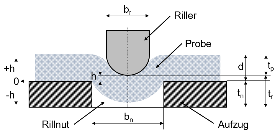
Fig. 1: Schematic view of the creasing process with the most important geometric variables.
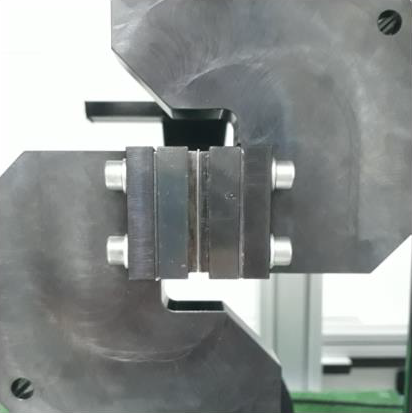
Fig. 2a: Sample in place on the out-of-plane shear test stand.
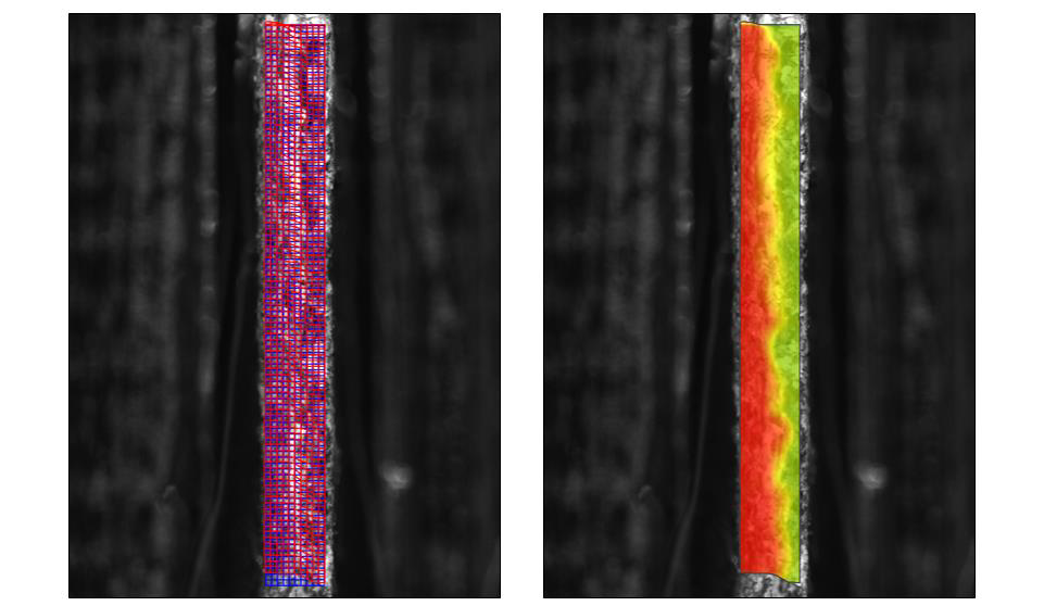
Fig. 2b: Shifts in the board material during testing: initial blue grid and shifted red grid (left), as well as coloured identification of the separation level (right).
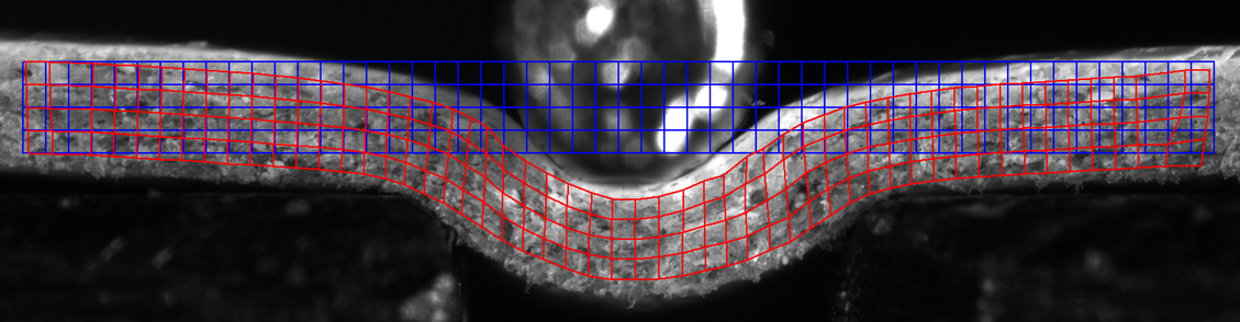
Fig. 3: Initial (blue) and deformed (red) measuring grids in a creasing operation for evaluation by means of optical strain field analysis.
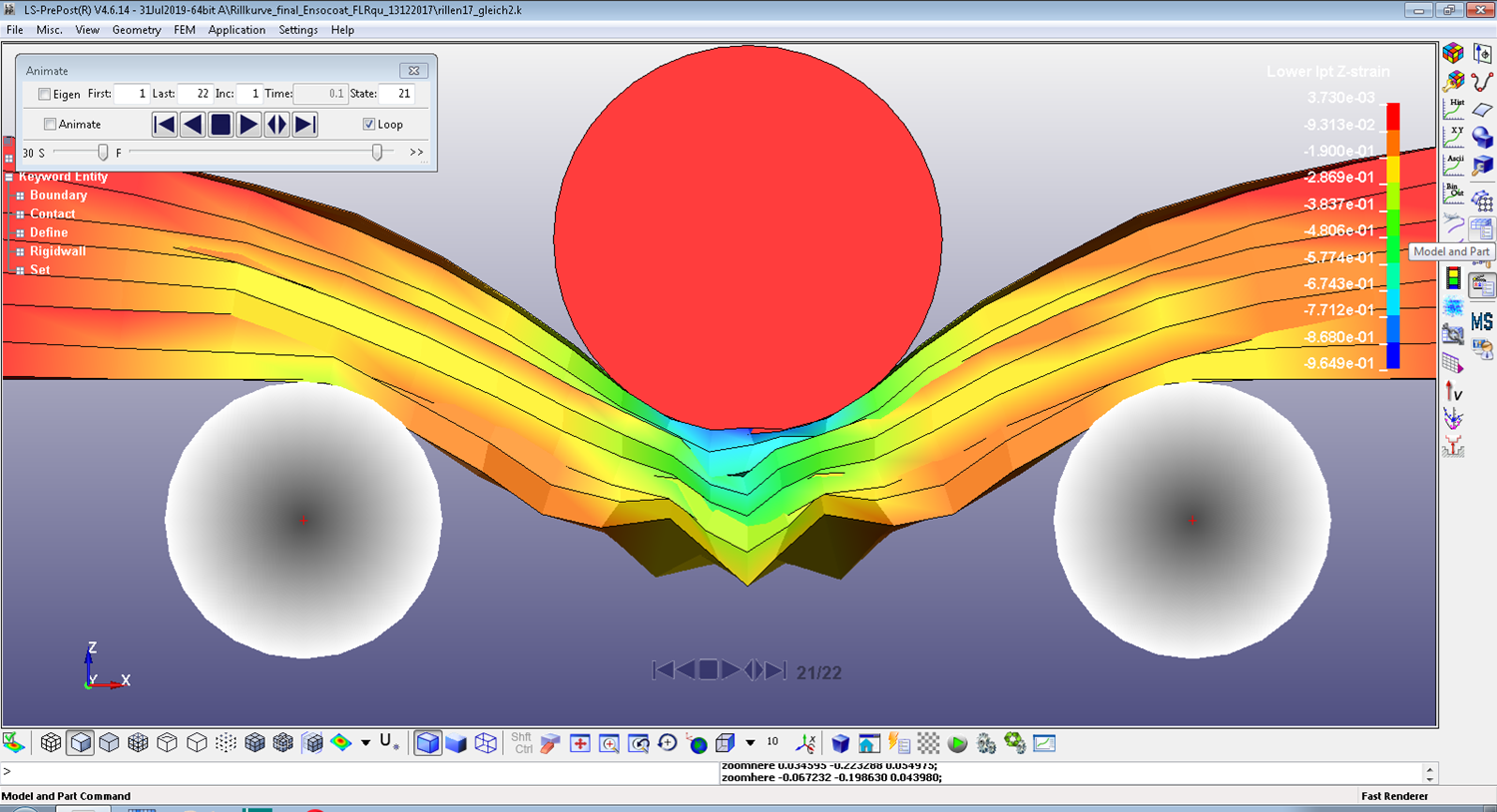
Fig. 4: Result of FE simulation: lateral strain (thickness compression) in each of the board plies as a result of the creasing process.
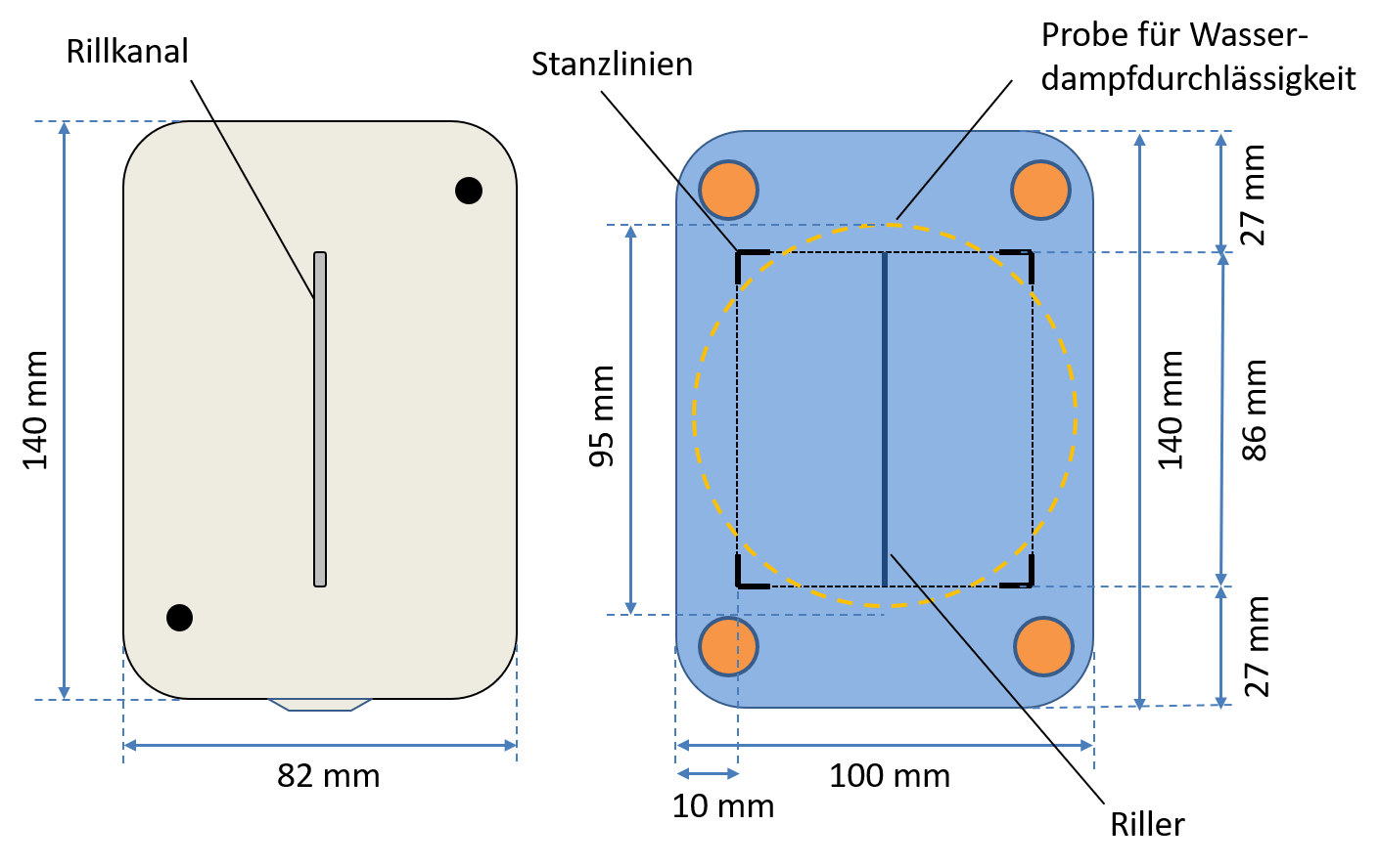
Fig. 5: Sketch of the cutting-creasing tools made for the testing of permeability to water vapours and hexane fumes.

Dr. Markus Kleebauer, PTS.

Benjamin Hiller, PTS.
Authors: Dr. Markus Kleebauer, Benjamin Hiller
Editor: sbr
Images: PTS
Content

